We have 4 traditional alternatives for power supply when dealing with discrete pedals (ie. analog pedals) chains:
- Battery power supply
- Wall wart adapter per pedal
- Daisy-chain power supply
- Isolated power supply
Battery powered Pedalboards
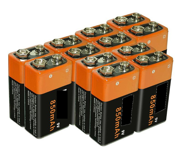
Batteries provide clean power if we are talking about noise, but they have obvious problems: They does not provide clean energy because we have to dispose the battery once it is exhausted, and if the batteries are not rechargeable the problem is bigger. Also batteries are the most expensive option even if rechargeable.
Wall Wart Adapter per unit
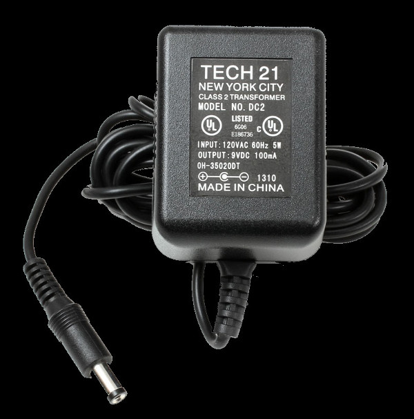
Wall warts are big, ugly, noisy and fail all the time, but they are very popular for one reason: They are cheap and you can find one anywhere. Space is a precious resource in Pedalboards, Wall Warts are usually a problem because they are big and if you plug one per pedal you will lose a lot of space.
Another common problem with wall warts is that they get accidentally disconnected all the time, specially in the middle of your solo.
Daisy-Chain Power supplier
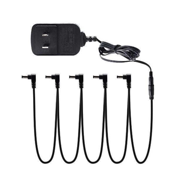
Power consumption of effect pedals is very low most of the time (with exceptions ie. Digital effects), so it was a matter of time before someone realized that one wall wart can power more than one pedal and one bigger wall wart can power a lot of pedals, this is called a daisy-chain. Sound good eh? But there is one new problem: Ground Loops. A chain of effects is a complex noisy device by nature and if you add multiple paths to ground (from the power chain and from the audio ground chain) you will get a lot of HUM noise.
Isolated Power supplies
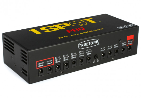
Isolated power supplies were designed to resolve the noise problem (ground loop noise) of daisy-chains. So the idea is to have one big power unit and provide isolated power to each effect. This solution works very well, it is clean and stable. the isolated PSUs tends to be big, but not as big as a bunch of wall warts. The problem with this kind of units are two: they are expensive and current (mA) limit is fixed per output because they have to be fully isolated, so if you have a pedal with 500mA consumption and a pedal with 50mA but your PSU have 8 outputs of 100mA each, your 500mA pedal will not work even if your PSU is rated at 800mA in total. Advanced PSUs cover most common power needs.
OGPSU: Open Ground Power Supply Unit
I have invented the term OGPSU (Open Ground Power Supply Unit) to describe a kind of wiring to solve the daisy-chain ground loops problem in Pedalboards. The idea is very simple and I wonder why no one has come to here before, I have tested this concept in several Pedalboards without any problem.
First, we have to understand the ground loop problem:
There are two sources of power in your effects chain, one is the power supply by itself, the other is the input audio signal. The output signal is the result of the combination of the two sources and here is the problem, your signal and the power supply share the same ground. Nothing new here, the thing is that if your power supply ground is not stable and clean, it will add perturbations to your signal, those perturbations will be present in the output as noise, usually HUM noise.
Now think about electricity as water, power supply as a water tank and wire as pipes, so your signal enters by one side of a pipe, then mixes with another bigger source (Power supply) and part of the combination go out to the other side of the pipe, but the remaining water returns to the power supply (tank) by another pipe. If the speed of the water return is fixed, the whole system is stable and very few perturbations are added to the output, but what happen if you connect more pipes of different length and diameter to the system to allow multiple paths to return the water to the tank? Well, the water will return to the tank in different streams with different speed and caudal, so the water in the tank will be very unstable, the waves created in the tank will propagate to the system and will be combined with your signal and this undesired combination is called noise. So what was the problem? Yes, you added multiple irregular return paths (ground loops). So what is the solution? Keep one single return path.
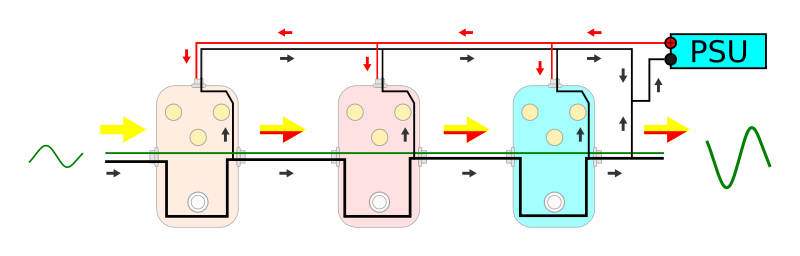
As you can see in the Fig 1, red arrows represent positive flow (DC), black arrows represent negative (ground) return flows (DC), and yellow/red arrows represent the audio signal (AC). If you follow the black arrows, you will find multiple return paths to the PSU and that means Noise.
Finally: OGPSU to the rescue
Now that we understand the problem, the solution is pretty obvious and simple: Eliminate unnecessary return paths from the circuit. But How? This will scary many people but the answer is actually pretty simple, just cut out the ground connection from the power supply input of each pedal, then connect the PSU Ground directly to the audio ground of the last pedal in the chain. Lets see:
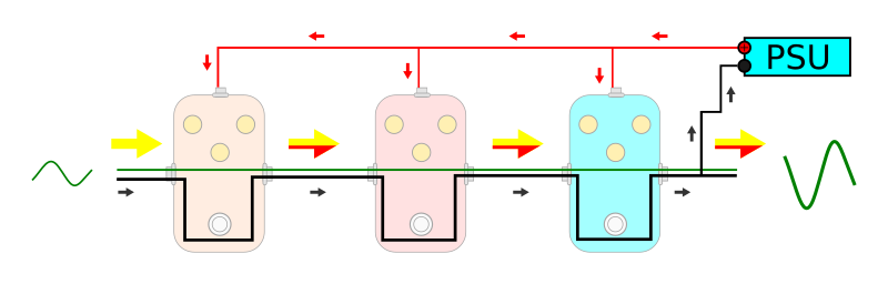
This works! I have used this wiring many times. It eliminates 100% of internal ground loop noise. But Ground loop is not the only noise source in this kind of circuit so now we have to concentrate only in filtering noise produced by the PSU itself, but this topic is for other post.
The advantage of this wiring schema is that you can buy a not too expensive PSU (make sure it is well filtered) and connect all your pedals like if it was a daisy-chain but without ground loops.
Pros
- Power (mA) will be distributed automatically across pedals, so you don’t have to worry about limited output power per output. If your PSU is rated at 1000mA, you can combine pedals up to 1000mA.
- Simplified wiring layout
- Not expensive PSU
- No Ground Loops
Cons
- One single positive voltage for all your pedals. If you have pedals that work at 18V, you need to add another PSU and connect them there.
- One single polarity, if you have pedals with inverted polarity, you need to add another PSU for them.
- You need to make your own pedal power cables or modify a daisy-chain cable.
I use this design in my custom Pedalboards with integrated power supply and in my custom Power Supply Units, so I provide the PSU and all the cables to use it.
Thanks for reading.
I’ve been hip this for years. I got a really great deal on a pedal steel player’s paddleboard and he had it made at Valley Arts… The old big-time little professional shop in LA. It had a custom power supply and that did have a separate 18 V to feed pedal or two I think one was the old Ibanez analog echo some of them ran on 18V. For the 9 V feed It ran a single line to each and used the ground that’s formed by hooking them all together. I’ve seen one that used Tip ring sleeve stereo connectors and had all the internal battery connections Shunted together. These were all old boards as I am old also, Old enough to have owned one of the first SESSUM pedalboards! Thanks for your post I think this will be catching on a lot more
Thank you for your comment. Yeah this is not new at all, eventually digital processors will replace analogs totally, but I am also an old man, so I enjoy things like wiring analog pedals. Using the metal enclosure as ground connection is a good idea if all the pedals have metallic enclosures connected internally to gnd, unfortunately these days some pedals have plastic enclosures. And young people are very afraid of removing a screw from any device. It is surprising who many people believe that such a device can kill them by electroshock.